
From AC to DC: How Diodes Make Rectification Work
Author: N
Reviewer: Baiyan
Alternating current and direct current are the two basic forms of electric current we use every day. Each has advantages the other cannot replace, so many applications require us to convert AC to DC or DC to AC. AC-to-DC conversion depends on a rectifier circuit, whose key component is the diode. Starting from that conversion process, this article examines the diode’s role in rectification. Along the way, it explores the principles of rectifier circuits, the relationship between ideal models and real components, and the use of Multisim as a simulation tool.
1. Introduction
AC and DC have different strengths and suit different applications. Most lighting and electric-motor systems, for example, use AC, while computers and mobile phones generally run on DC. Converting between the two lets us supply each device with the electrical characteristics it needs.
This article looks at how alternating current becomes direct current. The key stage is rectification, which relies on the electrical behavior of diodes. Multisim simulations help clarify the connections and differences among ideal circuit models, real circuit components, and complete modules.
We will proceed from the basic properties of a diode, to the way rectifier circuits exploit those properties, to the role of rectification in AC-to-DC conversion, and finally to Zener diodes and regulated DC power supplies.
2. Basic Properties of Diodes
A. Basic Construction and I–V Characteristic of a Diode
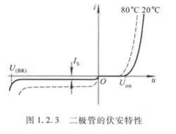
A diode is an electronic component made from a semiconductor such as silicon, selenium, or germanium. It conducts in only one direction: under forward bias, current flows from the anode to the cathode; under reverse bias, the diode blocks current. In this sense, a conducting or nonconducting diode behaves like a closed or open switch.
B. Equivalent Circuits for a Diode
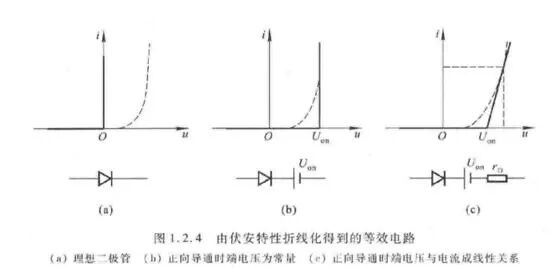
As the figure shows, a diode has a nonlinear current–voltage (I–V) characteristic, which complicates circuit analysis. Under a given set of conditions, we can simplify the problem by replacing the diode with linear elements that approximate its behavior. This substitute is called an equivalent circuit, or diode model. Different regions of the I–V curve give rise to several useful models.
3. How a Rectifier Circuit Uses Diode Properties
To keep the analysis focused, we assume a purely resistive load and use the ideal diode characteristic shown by the solid line in Figure 1.2.4(a) of Section 2, “Basic Properties of Diodes.” In this model, the forward voltage drop is zero when the diode conducts, and the reverse current is zero when it is off. For the same reason, the simulation uses a suitable AC source directly rather than first passing the input through a transformer.
A. Alternating Current
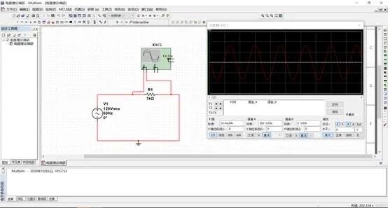
Alternating current, or AC, reverses direction periodically over time. The example below has a sinusoidal waveform.
B. Single-Phase Half-Wave Rectifier
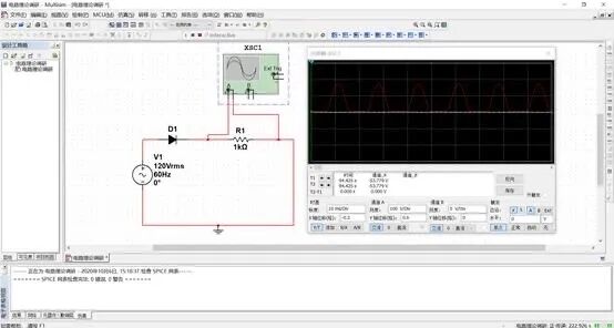
As Section 2 explains, a diode conducts under forward bias and blocks current under reverse bias. Placing an ideal diode D1 in series with the load resistor R1 therefore produces a voltage across the load, and a current through it, that pulses in only one direction. This is the simplest rectifier: the single-phase half-wave rectifier.
C. Single-Phase Bridge Rectifier
Because a half-wave rectifier discards half of each cycle, practical circuits more often use full-wave rectification. The single-phase bridge rectifier is the most common design.
A single-phase bridge rectifier contains four diodes arranged so that the voltage across the load and the current through it maintain the same polarity throughout the V1 cycle. Different pairs of diodes steer current through the load during the positive and negative half-cycles. The circuit model is shown below:
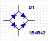
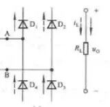
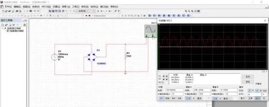
Connecting the single-phase bridge rectifier (1G4B42) produces the waveform below:
4. Using a Rectifier in an AC-to-DC Circuit
A. Direct Current
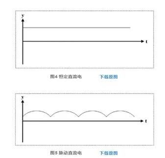
The output obtained above is called pulsating direct current. Its magnitude changes over time, but its direction does not. This differs from the constant direct current introduced in high-school physics, whose magnitude and direction remain fixed, as with ideal constant-voltage and constant-current sources. Real DC need not be perfectly constant: the terminal voltage of an ordinary dry cell, for example, gradually falls during use even though its polarity stays the same.
B. Rectification + Filtering + Voltage Regulation
A rectifier produces an output with only one polarity, but that output still contains a large AC component and cannot power most electronic circuits directly. A filter is therefore placed after the rectifier to smooth the pulsating DC voltage.
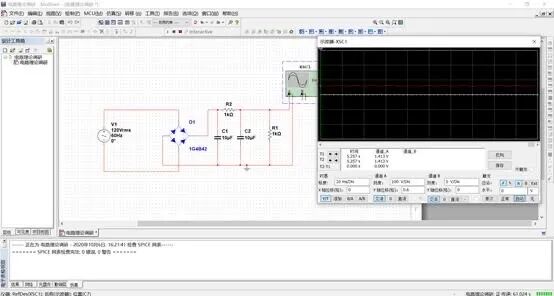
A rectifier and filter can convert a sinusoidal AC input into fairly smooth DC, but two problems remain. First, the average output depends on the RMS input, so any fluctuation at the input appears at the output. Second, the rectifier and filter have internal resistance. When the load changes, the voltage drop across that resistance changes, pushing the average output in the opposite direction. A voltage regulator is needed to keep the DC output stable.
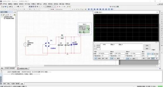
Adding a Zener diode (1N4884) in parallel completes the rectifier, filter, and regulator stages, producing the desired smooth, stable DC output from the AC input.
5. Further Exploration: Zener Diodes and Regulated DC Power Supplies
A. Zener Diodes
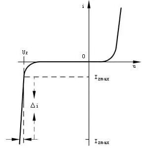
A Zener diode is a silicon junction diode designed to operate in reverse breakdown. Within a specified current, or power-dissipation, range, the voltage across it remains nearly constant. This property makes Zener diodes useful in voltage regulators and clipping circuits.
B. Regulated DC Power Supplies
A DC power supply takes 220 V mains electricity as its input. The required DC voltage is usually much lower than the RMS mains voltage, so a power transformer first steps the voltage down before further processing. The needs of the downstream circuit determine the RMS voltage at the transformer’s secondary. Some modern circuits omit the transformer and use other methods to step the voltage up or down.
The rectifier converts the AC voltage at the transformer’s secondary into DC: it turns a sinusoidal voltage into a unidirectional, pulsating voltage. The half-wave and full-wave outputs are shown below:
Both waveforms contain large AC components that can interfere with the load circuit. Ripple from the power supply may, for example, mix with an amplifier’s input and be amplified until it exceeds the useful signal at the output. The rectified voltage therefore cannot power an electronic circuit directly. The waveforms shown here are measured before a filter is connected; adding the filter changes their shape.
A low-pass filter smooths the output and reduces its voltage ripple. Ideally, it would remove the entire AC component and leave pure DC. Because the filter is passive, however, connecting a load inevitably affects its performance. For circuits that do not require high stability, rectified and filtered DC may still be adequate.
After rectification and filtering, the output is DC with a relatively small AC component. Its average value still changes when the mains voltage or load changes. A regulator isolates the output from those variations and provides the required stability. This is the basic principle of a regulated DC power supply.
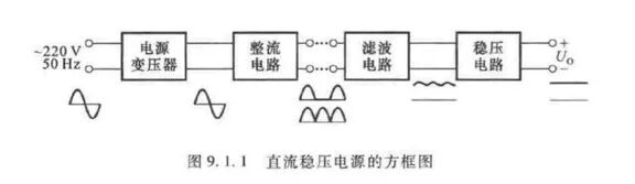
The block diagram above shows the same sequence discussed earlier: rectification, filtering, and regulation. The diode is the central component. In a practical supply, the main difference is that the 220 V mains input must first be stepped down.
6. Conclusion
At the heart of a complex regulated DC power supply lies a tiny diode. The electronic products and household appliances around us may be large and complicated, but they are built one seemingly insignificant component at a time. Small parts can do remarkable things. Assembling them into a circuit, and then into a working product, is almost like building a country: each circuit is its own kingdom, and every component is one of its citizens. To use those components well, we must understand how each is made and what governs its behavior. A circuit comes to life only through careful analysis and planning.
This, I think, is why we study subjects such as Circuit Theory, Semiconductor Physics, and Physics of Semiconductor Devices. Starting from first principles helps us develop an intuitive feel for components, so we can use them confidently to build the circuits we have in mind.
References
[1] Yuan Chen. “Principles of Conversion Between Alternating and Direct Current” [J]. Electronics World, 2018, (19), 21–23.
[2] Tong Shibai and Hua Chengying, eds. Fundamentals of Analog Electronics, 5th ed. [M]. Beijing: Higher Education Press, 2015.
[3] Gao Jixiang, ed. Analog Electronic Circuits and Power-Supply Design [M]. Beijing: Publishing House of Electronics Industry, 2019.
 爱发电(点击图片跳转)